S and S Machine
Bicycle Torque Couplings (BTCs)
Your Travel Bike........Your Only Bike!
Bicycle Torque Coupling Deflection Test
These tests demonstrate that in torsion, tension and bending, a tube
that has an S and S Bicycle Torque Coupling installed will be stiffer than
a plain section of Reynolds 531 bicycle tube. The details of how the fixtures
work are included. For a quick review of the results, see the photos with
the purple dots. The dots show how much flexing takes place. In each test
there is more flex in the plain tube than in the tube section with the
coupling. The results and conclusions for each demonstration are also included.
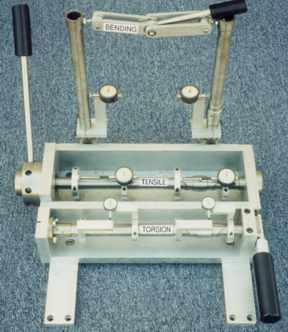
Combination torsion, tension and bending test fixture.
Front view
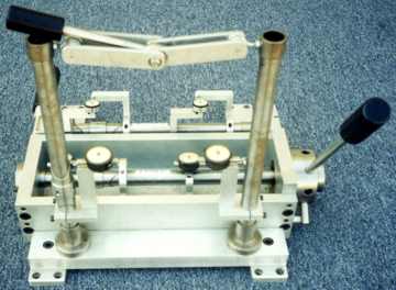
Back view
The combination test fixture
- This fixture is actually three independent test fixtures mounted on
one base for compactness. We originally made it as three fixtures but later
combined them as our booth space at bikes shows became limited.
- Only one test is performed at a time.
Standard test criteria
- Each test compares a 4 inch section of Reynolds 531 tube to a 4 inch
section of Reynolds 531 with an S and S Bicycle Torque Coupling
installed.
- In each fixture a single load is applied to both test sections simultaneously
so that the force is equal in both samples being compared.
- In each test the coupling was tightened with our standard 6" spanner
wrench.
- Flex is measured with dial indicators. The purple dots represent the
amount of indicator movement in thousandths of an inch.
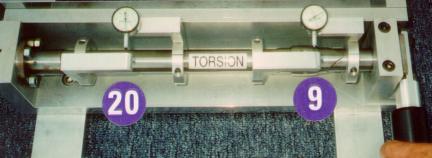
Torsion test fixture
 Tube only Tube with coupling
Torsion test
- Fixture layout: The fixture has a tube that is bolted in solid
on the left end and is free to rotate in a bearing on the right. A lever
is attached to the end of the tube beyond the bearing.
- Application of load: When the lever is pushed down it twists
the tube.
- Measurement method: A collar with an arm is attached to the
tube and a dial indicator is attached to the arm. A second collar with
an arm is attached 4 inches away. The indicator plunger from the first
arm rests against the second arm. Two indicator assemblies are attached
to the tube. One is placed in the plain section of tube and the other is
placed in the coupled section of tube with a collar on each side of the
coupling. When the lever is pushed down the arms on the collars move closer
together. The indicator shows the amount of twist between the arms. A stiffer
section will allow less twist.
- Results: There was.020" twist in the tube section without
the coupling. There was .009" twist in the section with the coupling.
- Conclusion: This test demonstrates that in torsion the tube
section with the coupling is stiffer than the plain tube.
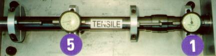
Tension test fixture
 Tube only Tube with coupling
Tension test
- Fixture layout: The tension test fixture has a tube that is
bolted in solid on the right and it goes through a hub on the left that
can slide but not rotate. A threaded collar with a lever is screwed onto
the hub until it bottoms out against the end of the fixture. (See the threaded
collar and lever in the first photo)
- Application of load: When the lever is pushed down it moves
the hub to the left which pulls on the tube.
- Measurement method: Two collars are clamped to the tube 4 inches
apart. A dial indicator is mounted to one collar and the plunger rests
against the other. Two indicator assemblies are attached to the tube. One
is placed in the plain section of tube and the other is placed in the coupled
section of tube with a collar on each side of the coupling. The dial indicators
show the amount of stretch between the collars. A stiffer section of tube
will allow less stretch.
- Results: The collars in the plain tube stretched .005".
There was .001" stretch in the tube section with a coupling.
- Conclusion: This test demonstrates that in tension the tube
section with the coupling is stiffer than the plain tube.
Bend test fixture
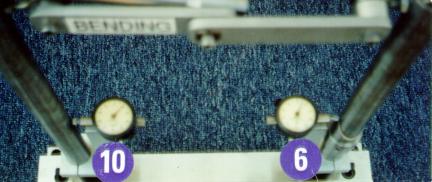 Tube only Tube with coupling
Bend test
- Fixture layout: The bend test fixture has two tubes mounted
vertically. One tube has a coupling installed and the other does not. A
linkage connects the tubes at the top. A lever controlled eccentric mechanism
is located in the center of the linkage.
- Application of load: When the lever is moved the eccentric mechanism
shortens the linkage which pulls the tubes together causing them to bend.
The mechanism holds the tubes together once the lever has been flipped
for a more accurate reading.
- Measurement method: A collar with a 4 inch vertical arm is attached
to the tube. A dial indicator is mounted on top of the arm. The plunger
of the indicator rests against the tube. An identical assembly is installed
on each tube and they are positioned on the tube the same distance from
the fixture base. The indicators show how much bending takes place in the
4" section of each tube. A stiffer section of tube will allow less
bending.
- Results: The indicator in the plain section of tube bent .010".
There was .006" bend in the coupled tube.
- Conclusion: This test demonstrates that in bending the tube
section with the coupling is stiffer than the plain tube.
Framebuilder list |
Cases |
Packing |
Photos |
Reviews |
Comments |
Retailer list |
Installation |
Specifications |
Cost |
Retrofit or new? |
Travel adventures
Contact Information
S and S Machine's Home Page