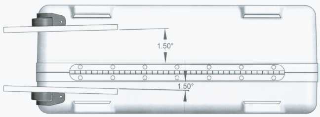
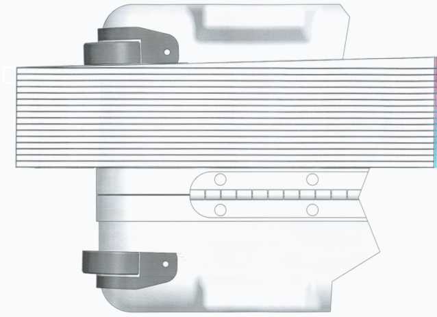
This is the bottom view of the case (note the hinge and feet).
This in an enlarged view of the wheel area of the case showing the desired
wheel alignment.
The S and S hard case has always been more stable when pushed rather than pulled. For those wishing to gain more stability when pulling the case (less stability when pushed), changing the alignment of the wheels will help a lot.
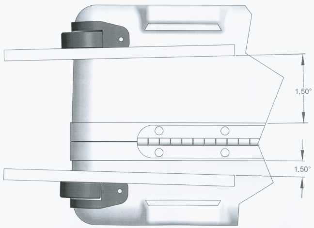
This is the bottom view of the case (note the hinge and feet).
This in an enlarged view of the wheel area of the case showing the desired
wheel alignment.
To change the alignment of the wheels, all of the wheel mounting holes must be slotted (elongated). The screws that hold the wheels in will need to be tightened well to keep the wheels from moving back to their original alignment.
It is also necessary to slightly enlarge the openings in the case where the wheels go to allow the wheels to shift sideways. Make sure that when cutting this opening wider, you don't go too far. Periodically check to make sure that the flanges on the wheel housing still cover the hole entirely.
The dotted lines in the image below show where material will need to be removed to change the alignment. If you have trouble visualizing this detail, print the image then fold the paper 90 degrees along an imaginary vertical line between the two details to give you a 3 dimensional view and that may help .Not drawn to scale.
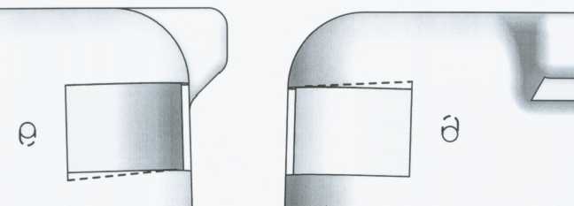
End view of case (note
foot)
Bottom view (note
foot)
Both views are of the
same wheel opening viewed from a different angle.
The other wheel opening needs to be done in mirror image
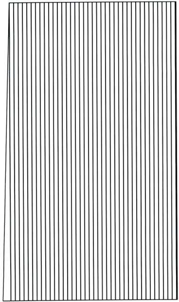
1.5 degree paper angle gage
(right click on this image then click on "print picture" to print this
gage)
If you don't have a way to measure the wheel angle, the gage that is provided here can be printed out then cut to the desired width as a simple means of measuring the 1.5 degree angle. Cut the printout along one of the parallel lines to the desired width to fit the case that you are modifying Hold one edge of the paper gage against the metal case frame and the other side against the wheel. By sliding the wedge shaped gage left or right, it is possible to make both edges of the paper to come into contact at the same time as shown below.
This image shows how the printed out paper gage is use to measure the wheel
alignment.
The wheel angle should be somewhere between 1 and 2 degrees (we used 1.5 degrees as a starting point) and it doesn't seem to matter if the angle on one wheel is greater than the other as long as there is about 2 to 4 degrees total when measured between the two wheels.
For example: If you have each wheel set at 1.5 degrees off the centerline of the case, the total between the two wheels will be 3 degrees.